
This year (2019) I thought that I would try something new, The Christmas Crank. Basically you spin a crank to light up a sequence of large Christmas lights to show how much Christmas spirit you have; the faster you spin, the more lights you light up. I was shooting for something like the strong-man sledge hammer games at the fair when you swing the hammer and try to ring the bell at the top of a pole. I had a couple of things I was shooting for with this project that I thought would be fun: 1) I was thinking it would be nice to make this prop a little more educational and maybe teach people along the way, 2) I tried to recycle/reuse as much as I could for this, 3) I wanted to show how hard it can be to create enough power to light up a few light bulbs (and not take electricity for granted), and lastly 4) I wanted to do this without any microcontrollers being involved. I am an embedded guy by nature, but I like to expand outside my comfort zone and wanted to make this as close to bare metal as I could. Besides the LM3914, the whole design is made with discretes and are analog by nature.
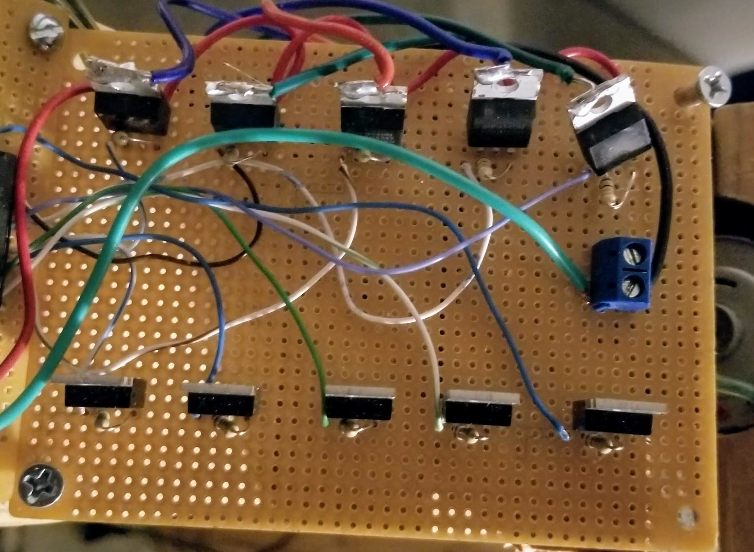
The lights are turned on via P-Channel FETs set up as a low-side load switches. I like to use low-side because then I don’t have power always on at the other end of the Drain. In this application, there is no power in the system at all unless it is being cranked, but it is just a habit, so I did it here. The LM3914 has open-collector outputs on the Lx pins. Because of this, the pins float when not “enabled” and are current sinks when they are. That is a 10k pull-up between the Gain and the Source on the FETs. When the Lx pin is not “enabled,” the pin will float, which means it will be weak-pulled high to the voltage on the Source pin (15_V_2 in this case). When “enabled,” The Gate will be pulled low, passing the 15_V_2 from the Source to the Drain; when this happens the bulbs will essentially be connected from 15V to ground, lighting them up.
 The LM3914 is a neat little part that has been around a million years (OK, maybe I am prone to exaggerations, it was released in 1980). As its wikipedia entry so succinctly puts it:
The LM3914 is an integrated circuit (IC) designed by National Semiconductor and used to operate displays that visually show the magnitude of an analog signal.
If you remember the old school audio receivers that had the LEDs on the front that would bounce up and down as the magnitudes of the signals in each of the different frequency bins fluctuated, that is essentially what this chip is doing. This IC is the brains of the entire project; it is going to monitor a voltage being fed into it, and then pull low the output pins to show the magnitude levels. I will use this functionality to drive the FETs and determine what lights should be on. I used 5 of the pins, but skipped the very first one (I was having some weird issues when I used it, so I went with L2-L6). In the pictures you will see further down in this post, I actually soldered up 10 total FETs, but after playing with different configurations and physical sizes of the display, I settled on the five.
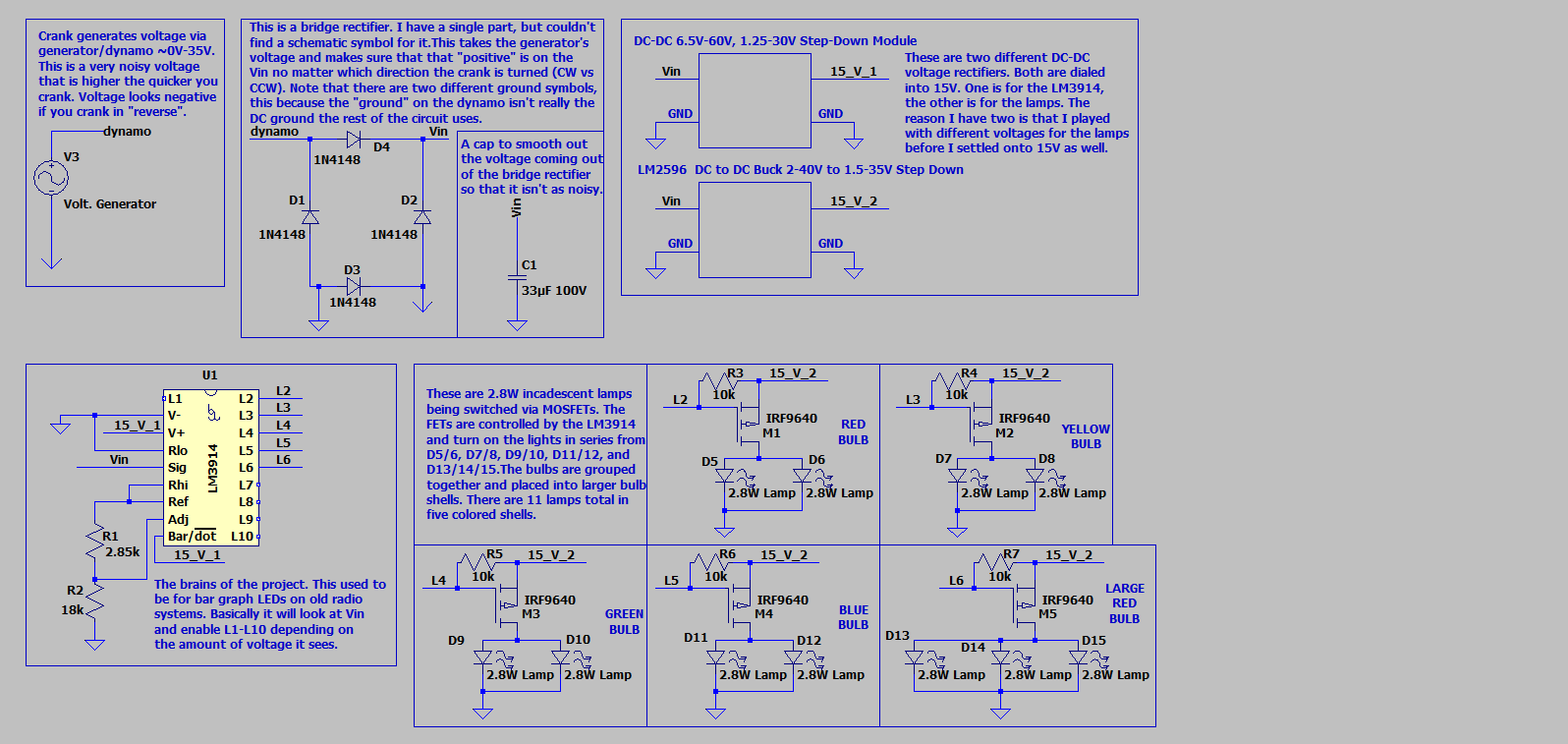
I tried to layout the schematic in a sort of left to right, top down approach with each section in its own box. I put comments in the schematic, but I will reuse some of them here as well:
The “crank” – This is a “generator” or “dynamo.” When you apply a voltage to a DC motor, it causes the shaft to spin due to the magnetic fields within the motor. Conversely, if you spin the shaft of that same motor, you should be able to produce a voltage on those same input pins. This is what a car’s alternator is doing to charge its battery, or an industrial windmill is doing to feed power back to the grid. Instead of a meaningful purpose like those two examples, I will be powering lights to test you Christmas spirit. It can generate ~0-35V of very noisy “DC voltage.” I use the term DC loosely as it is not a steady voltage at all, but it is certainly not AC. The faster you crank, the higher the voltage, and the more load you are driving the harder the crank becomes to turn. If you spin the crank in the opposite direction, it will produce a “negative” voltage.
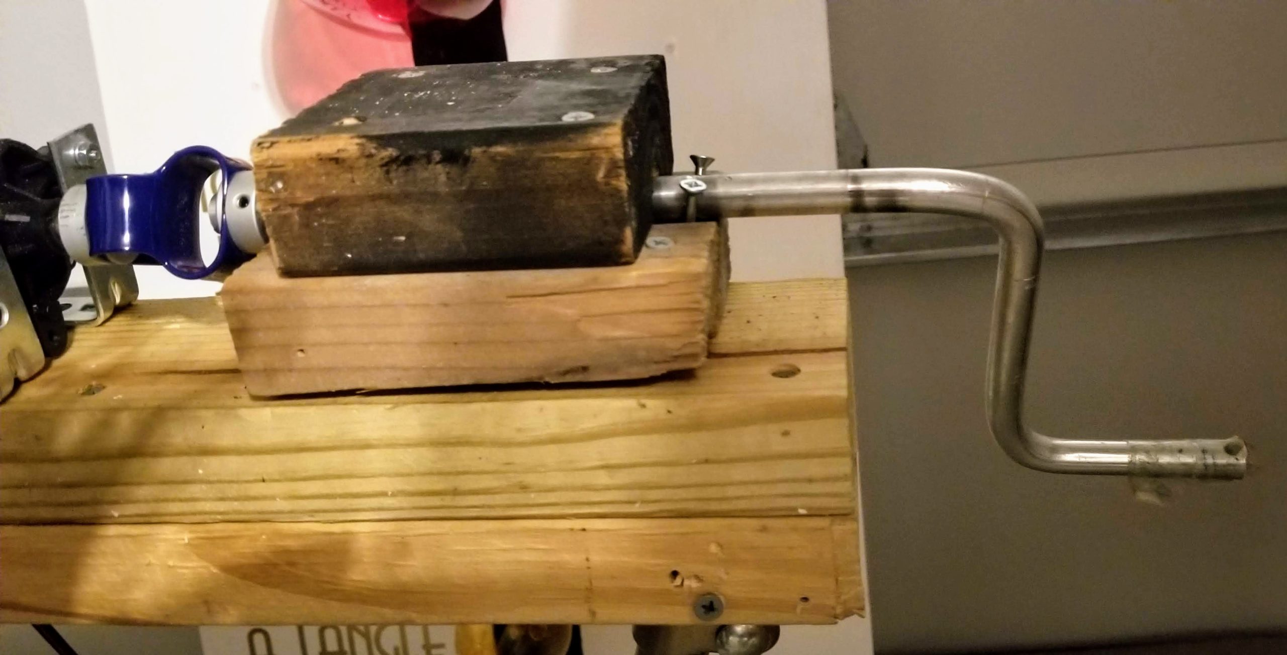
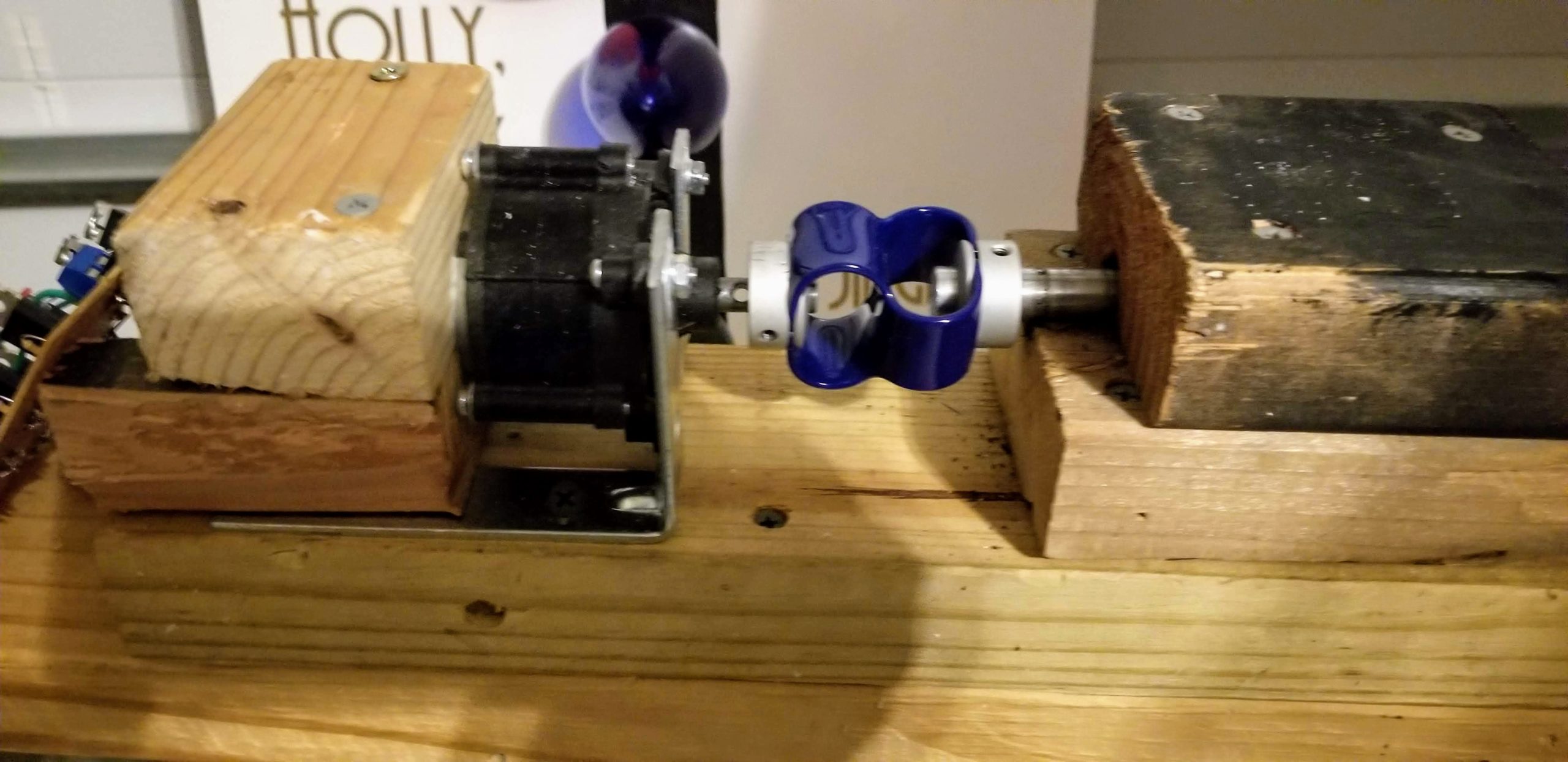
I purchased this dynamo on eBay a few years back and finally got around to playing with it. You can find a lot of this hardware online directed towards the home windmill crowds. The end of the dynamo had a small shaft sticking out of it that I originally was directly connecting to. I bored a hole in the end of a small Aluminum rod and then attached it to the dynamo’s shaft with a pin to hold it into place. I bent the rod into a handle shape and then I let my 4 and 7 year olds put this this through its paces and decided that this was not going to last a season with pressure being put on that rod is no many different ways. My solution was to connect the handle to the dyamo’s shaft through a “convex elasticity Coupling” part I also found on eBay. I hadn’t really seen these before, but while looking for solutions to my issue, I ran across it and have been very happy. Now I didn’t need my handle to be perfectly aligned with the shaft, or worry about too much stress being passed through the handle to the shaft. It is over-priced, but it fit the bill.
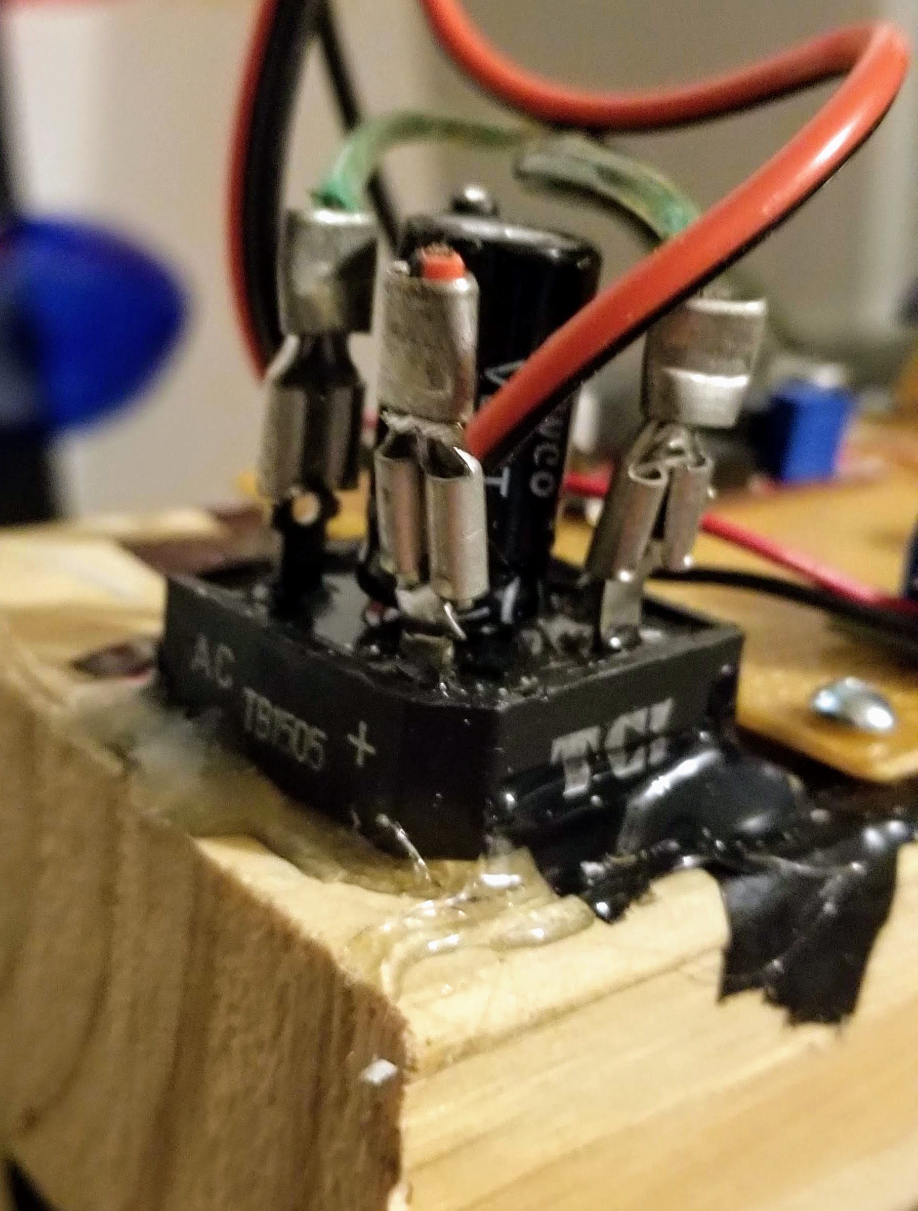
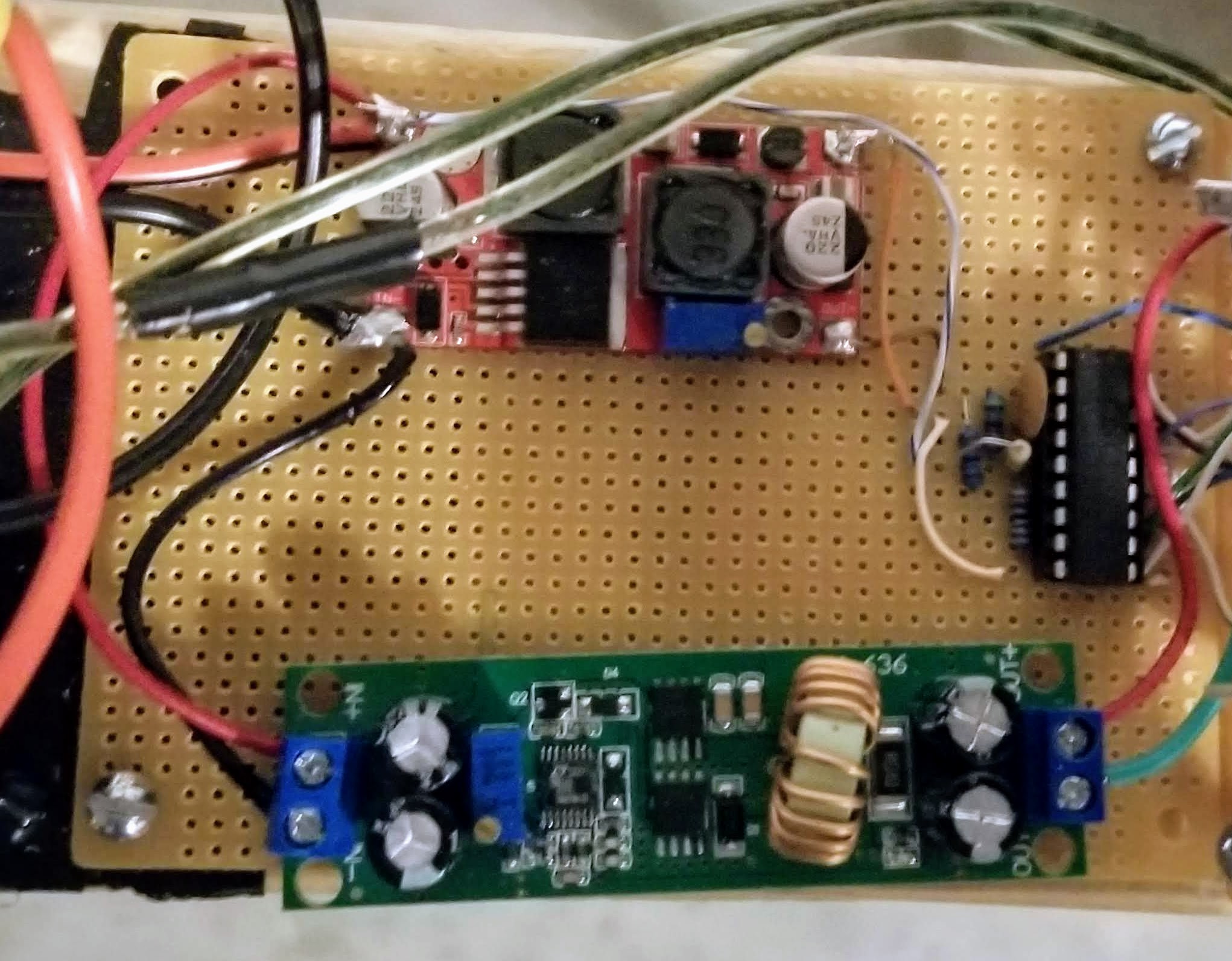
 Bridge Rectifier – I put a bridge rectifier on the output of the dynamo (I just like using that term for some reason) because I didn’t know if a kid would be turning the crank clockwise or counter clockwise. By using the bridge rectifier, I could be confident that the input to my actual circuit would always be positive. There is some loss due to the way the bridge rectifiers work, but it will be minimal for this application. On the output of the rectifier I slapped a beefy cap to help smooth out the fluctuations being generated by the user. I’ve had this rectifier lying around since my first Christmas project (my original Christmas Countdown that is on my webpage) back in 2004.
Voltage Regulators – There are two different regulators in the system that are both putting out 15VDC. At the end of the day, they are both taking the dirty DC voltage off of the rectifier and producing 15VDC for the system. The reason there are two doing the same thing is that originally I had the LM3914 running off of 15V, and the lights running off of a different voltage. Once I went aways from high powered LEDs to the incadecent bulbs I ended up with, I happened to be back at 15V on the second regulator as well. Both of these devices were purchased off of Amazon.
LM3914 – I went into some details about this above, but it is setup via the resistors in the schematic and there are great examples of people playing with it all over the net.
 IRF9640 P-channel MOSFETs – Yet again, other parts from my junk drawer. I pulled down some schematics from the net to set them up, but it is pretty straightforward.
 2.8W incadescent lamps – After not being happy with my high-powered LEDs, I ended up going with these small lights that used to be used in flashlights a lot back in the day. I picked up a set of them as well as the bases with pre-soldered wires on them from Amazon. Each colored “bulb” that a kid is trying to light up has two of these lights in them, except the top one has three. So there are 11 total bulbs in play.
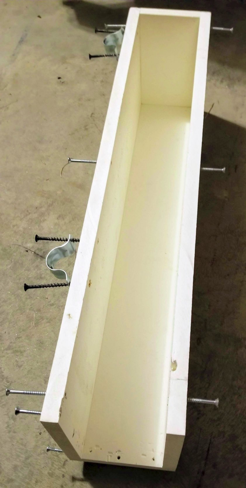
The enclosure for the design is used from leftover PVC trimboard from when my deck was built. This is the first time I’ve ever worked with it, and I REALLY liked it! I have a bunch more scrap and plan on using it again. I made the enclosure so that it can pop off as needed via screws all around it. It is screwed into the 2×4 base of the project.

The colored “bulbs” that are being lit up by the incandescents are from WalMart and intended to be used in a yard. I pulled out the C7 bulbs that were in them, and retrofitted mine in place. My wife broke out the CriCut and did some lettering for me.
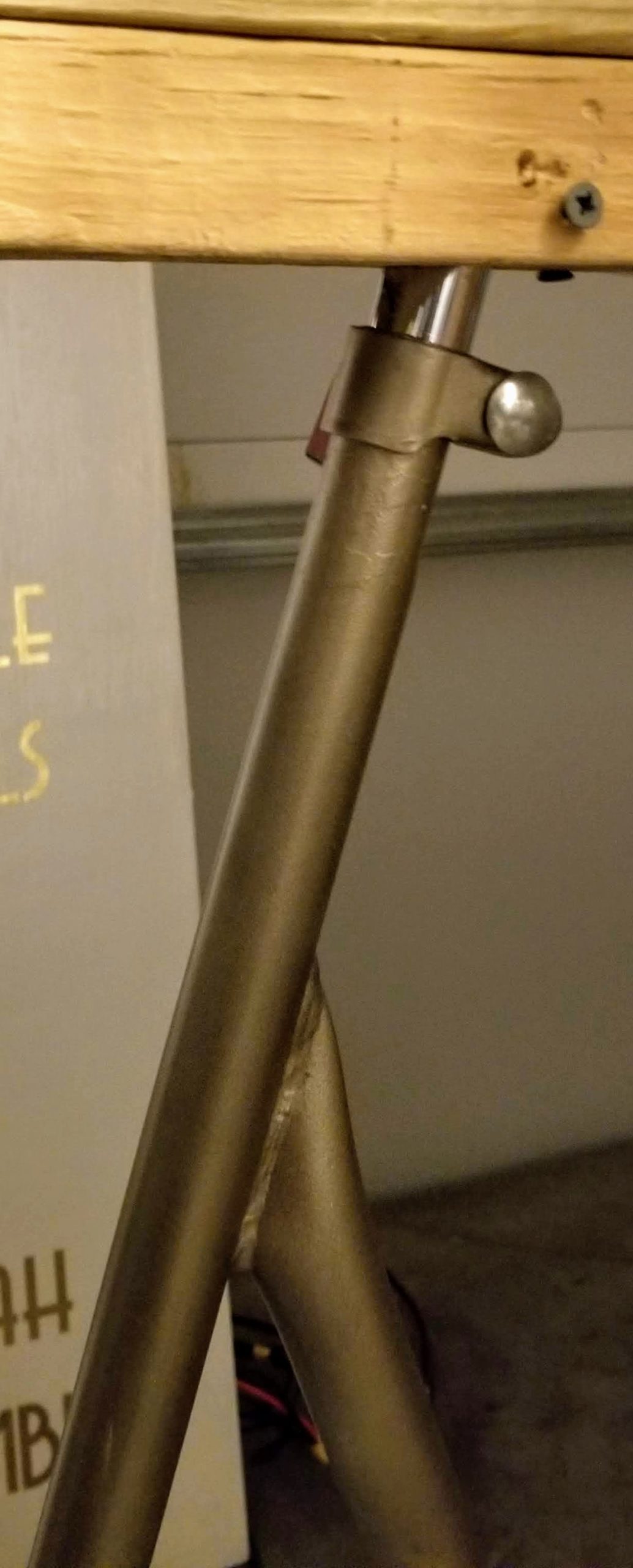
 The project box with the crank and electronics sit on an old school exercise bike I got from someone’s garbage. This was the kind that had an actual bike chain and everything (VERY old school). I stripped it down and pained it gold. Then I drilled holes into the box’s base and mounted into it the rod that the seat was attached to as well as the bottom part of the handles. With that mounted to the 2×4, I can wiggle it back into place (a bit of a pain since one rod goes vertical and the other at an angle) and bolt it to the bike with the original hardware. I can put it on and remove it at will, but I probably won’t do it often.

 The whole display worked like a charm once I added reinforcement to the back of the display box to the ground via pipes sunk 3ft down. Kids absolutely loved it and it stood up to the wear and tear better than I thought it would. I was happy with this addition to the display this year.
Thanks for reading this far down and I hope this was at least slightly enjoyable and maybe sparked some ideas for what you could do in your yards next year. Feel free to reach out with question or comments. To wrap up, there are two videos. The first is my rambling, sometimes incoherent explanations of things (ignore when I said 5VDC was being generated by a regulator, I meant 15VDC), and the second is my kid and wife taking the very first cranks testing their Christmas Spirit the night it went out.