
Background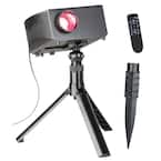 In an attempt to step up our Halloween game, we wanted to use AtmosFX’s projector videos of Jack-O’-Lantern Jamboree . This seemed like a straight-forward project, but of course ultimately involved more work than was originally anticipated.
The Issue
The crux of this project was to automate a projector to perform a series of steps on power up to mimic a human touching buttons so I wouldn’t have to do it every night, but I had a hard time finding outdoor projectors that were reasonably priced. My original plan was to use a cheap $45 projector and put it into a Rubbermaid bin with an IR light bulb to keep the temperature at a reasonable level (without adding any actual light to the surroundings). Since an IR bulb is in the infrared light spectrum (like most TV remotes), humans can’t see it; but being of the incandescent variety, it will still produce heat like old style light bulbs. I was going down this path because I was concerned with the temperature in the bin due to wanting to use it for our Christmas display as well as for Halloween. After buying supplies (to include temperature monitoring circuits, bulbs, and a raspberry PI to control everything), I decided that (as usual) I was making this project much more difficult than I needed to.
The Solution
Enter the LightShow CineMotion Projector. This is a projector that is no longer sold, but is very heavy duty and was designed to sit outside in the elements (so no worries about the bulbs cracking if they got wet). I found someone selling two (new in box) on eBay, so I picked them up. They are a little more expensive than your run-of-the-mill cheap projectors, but it is certainly better made, and designed to work outside. This device has some canned built-in animations, but can also play videos off of SD cards, USB, or use an HDMI connection.
The CineMotion projector will automatically start running once power is applied (which is awesome for my needs), but the major downside is that for some reason, after it has warmed up, it goes into whatever the last canned, built-in video was played on it; I couldn’t find any way to make it default to something of my choosing (like from an SD card).
The Solution
To get around this problem I considered spoofing the remote like I did on another projector project (**TODO** writeup that project), but didn’t really like that idea as there is a good chance that the signal wouldn’t register with the “remote” being so close to the IR receiver on the projector; so I decided to pursue a more hardwired solution. I took apart the projector (that was a multi-night ordeal due to the deep cavities that the screws are housed in) and had a look around inside. It is a very simple design that is basically the electronics for the projector/bulb, the very small PCB for the IR receiver, the main board, and the PCB that has the control buttons from the top of the unit on it. I tried looking for a micro SD card slot on the unit somewhere that was maybe storing the videos, but came up empty (I assume they are saved in a flash IC on the main PCB). The next step was to understand how the buttons on the top of the unit controlled the system. The buttons are momentary push buttons and their functions are nicely labelled in the silkscreen to make debugging easier. Pretty much the only other things on there were SMD resistors and LEDs.
The Slick Button Design
This button design is pretty slick and I’ve seen it used in other places (including other cheap home projectors I’ve taken apart). With only a handful of push buttons, a few LEDs, and a couple of resistors, this PCB can control the main board over a small handful of wires (as opposed to a dedicated wire per button). A quick explanation of it can be found here but I’ll explain it some more below. There are 4 wires on the board: power, ground, “K0”, and “K1”; with K0 and K1 as the data data wires for all the buttons. In a setup like this, K0 and K1 are usually inputs into a pair of ADC pins on a microcontroller. The microcontroller then monitors the pins and looks for changes in the voltage so that it knows what button was pressed. The buttons have specific resistors connected to them to act as a voltage divider. I won’t go into the details of voltage dividers (read here if interested), but essentially each push of the button causes a different voltage to be on the K0/K1 wires, and the microcontroller can determine which button was pressed. One downside to this approach is that you cannot press more than one button at a time without picking some very exact resistors with very accurate ADCs, but for this application it does not matter.
Here is a quick drawing about how something like the buttons on this projector are setup.
What I am trying to show in the drawing above are 5 push buttons on the bottom of the picture (PB1 – PB5) connected to ground through various resistors (R2 – R6). On the other side of the buttons is another resistor (R1) connected to a voltage (5V in this example), and in between the buttons and the upper resistor is where our K0 and K1 wire would be on the PCB in the projector. “Rx” in the equation above is where you would substitute R2, R3, R4, R5, or R6’s resistor value depending on which button you pressed.
When the projector is powered on and no buttons are pressed, the 5V is going through R1 and straight into the ADC. Since no one has pressed the push buttons, they are all in an “open circuit” state and no current can go through their bottom legs to ground, so you can imagine that they aren’t there at all. That means that the microcontroller’s ADC will read 5V on the “ADC in” pin (K0 or K1 on our PCB). So if the microcontroller reads the pin and see 5V, it knows that no buttons are currently pressed.
Now, let’s assume that a person pressed the button PB1. While they are pressing the button, PB1 will act as a “short” and will allow current to flow through R2 and into ground (all other buttons are still opens). When this happens, we will have a voltage divider with R1 on the top, and R2 on the bottom. Using our example drawing above, we can replace Rx in the equation with R2. We know that R2 is 10kΩ, so if we assume that R1 is also 10kΩ, we can use the voltage divider equation to figure out that the ADC pin would see: ADC = ((5V x R2) / (R1 + R2)) = ((5V x 10kΩ) / (10kΩ + 10kΩ)) = (50kVΩ / 20kΩ) = 2.5V. So if the microcontroller reads the pin and sees 2.5V, it knows that a person has pressed PB1, and it can react accordingly.
Another example would be if someone pressed PB3. Using what we learned above, and assuming that R1 is still 10kΩ, we replace Rx with R4 and we can determine that the ADC’s voltage would see ((5V x 2kΩ) / (10kΩ + 2kΩ)) = (10kVΩ/12kΩ) = 0.833V. So if the microcontroller reads the pin and sees 0.833V, it knows that a person has pressed PB3, and it can react accordingly.
The same process is true for all the other buttons. You will notice that the resistors are roughly half the value of the resistor on its left, and that the resistor all the way on the right is 0kΩ which will read as 0V at the ADC when that button is pressed since it will be directly connected to ground.
This is a picture I’ve previously taken from a different projector that is using the same process:
This is the actual board from the projector and you can see where I soldered the ground wire (green/white) and K0 and K1 (orange and orange/white):
Now to Recreate This
I didn’t want to lose the capability of the actual buttons on the top of the projector, so I decided to mimic a second set of push buttons using my trusty Arduino Nano and some mechanical relays. To accomplish this, I tapped off of the ground, K0 wire, and K1 wire on the PCB, and ran them to a perfboard. Ground is needed since all circuits that are interacting together must have the same reference point (read here). On the perfboard I recreated the resistor setup like on the PCB, but set it up for just the seven buttons I needed for my operation (home, OK, left, right, up, down, and volume up). Next, I wired up an Arduino Nano to 7 relays, and the output of the relays to the perfboard. To recreate someone using the actual buttons on top of the projector, I followed the series of steps I would have done by hand, and programmed the Arduino to follow those steps (but trigger the various relays instead of a user pressing a push button). Once the projector is up and running, the Arduino’s work is done and it just sits there for the rest of the show twiddling its digital thumbs.
Some Pictures
In this next photo, you can see my perboard. You can see the orange, orange/white, and green/white wires going to the bottom of the screen, these are the ones going to the PCB in the projector. The big black cable in the middle of the screen that has a black and red wire coming out of it are 5V and ground from a USB cable. This is powering the relays. The resistors in the photo are the ones recreating the same values on the PCB. You can see the orange and orange/white wires coming off of the two different sets, these are K0 and K1:
Next is a a closer (and blurrier) shot of the relays. The relays are replicating the push buttons. When not doing anything, it is an “open circuit” like I mentions above. When the Arduino enables one of the relays, it become “closed” and will complete that leg of the circuit. A short time later (say 300ms), the Arduino will disable the relay and it will be like the person stopped pressing the button:
Next is an image that shows the Arduino Nano. It is getting its power via the red USB cable. There are 7 pins that go to the 7 relays and also a ground wire:
The code can be found here.
**TODO**: Show video of the projector starting up.


